In a system composed of a RaspberryPi powered by an ATX power supply unit, the goal of this circuit is to allow to power on or power off the system with a single push button
Functional presentation
Below are detailed the circuit running steps
Power on
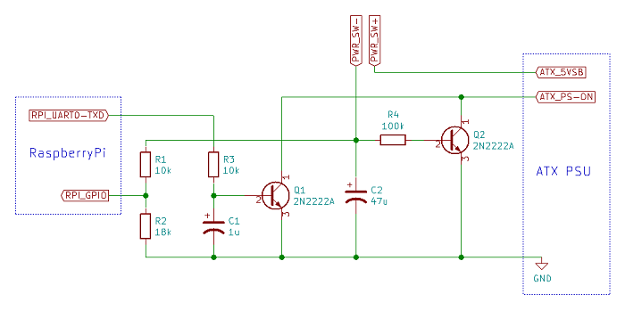
This circuit acts on the ATX_PS-ON ATX PSU pin to trigger its power on or power off.
By default, this pin is set to 5V, which means the PSU is stopped.
To power on the PSU, the circuit has to set ATX_PS-ON to the ground. When the push button is activated, the Q2 transistor sets ATX_PS-ON to the ground, which triggers the PSU power on and the RaspberryPi startup
System running
At startup, the RaspberryPi set its RPI_UART0-TXD pin to 3.3V, acting on Q1 transistor which keeps the PSU active by keeping ATX_PS-ON to the ground.
However, it may take some time before RPI_UART0-TXD goes to 3.3V (2.6 seconds on RaspberryPi 3). The RC sub-circuit on Q2 base is designed to maintain the transistor saturation enough time. The C1 capacitor absorbs voltage variations on RPI_UART0-TXD pin, which is useful if the RaspberryPi UART is used because it keeps the system active
System shutdown
A new pression on the push button is detected by software on the RaspberryPi by reading an input GPIO pin, the system shutdown can then be performed.
Once the RaspberryPi is stopped, its PCB remains powered but the RPI_UART0-TXD pin goes to the ground, Q1 is then cutted-off and the PSU stops
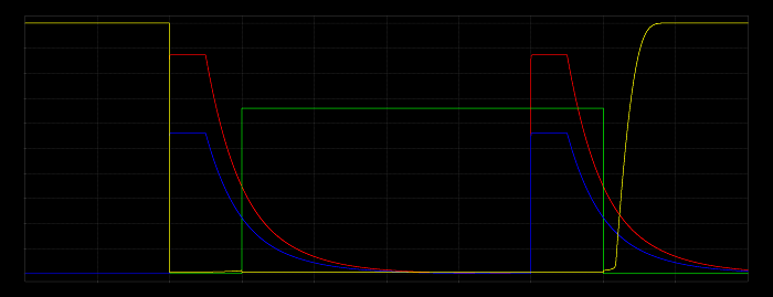
X: 2s / div
Y: 0.5v / div
ATX_PS-ON (measure)
PWR_SW (simulation)
RPI_GPIO (measure)
RPI_UART0-TXD (simulation)
RaspberryPi settings
RPI_UART0-TXD pin set to 3.3V while running
Through an SSH client, login on your RaspberryPi
First, configure the RaspberryPi to set RPI_UART0-TXD to 3.3V while running, to keep the PSU active
To do this, edit /boot/config.txt and add at the end: enable_uart=1
RaspberryPi stop triggered by GPIO
To allow the push button to trigger the RaspberryPi shutdown, the circuit has to be connected to a GPIO
Download the script
You can edit it to change the following values:
- HOLD_TIME: time to keep the button pressed to trigger shutdown (this value is distorted by C2 which keeps the level for a while after the button is released)
- PIN_NB: GPIO number to use
Copy the script to /usr/local/bin
Make it executable:
sudo chmod +x /usr/local/bin/rpi_shutdown.py
Install its dependencies, like gpiozero:
sudo apt-get -y install python3-gpiozero python3-pkg-resources
Enable it at the system startup:
sudo crontab -e
Add the following in the opening file:
@reboot /usr/local/bin/rpi_shutdown.py &
This script has been written according to the following documentation:
https://gpiozero.readthedocs.io/en/stable/recipes.html#shutdown-button
Properly reboot your RaspberryPi:
sudo reboot
You can now connect the circuit to the RaspberryPi and to the PSU and test the following:
- the PSU is kept active as expected by the RPI_UART0-TXD RaspberryPi pin
- pressing the button triggers the RaspberryPi shutdown, which stops the PSU
Ressources
 Download schematics
Download Kicad project
ATX module simulation (french version)
Instructables
 accueil
 nouveau
 cours html
  cours pdf
 cours doc
 cpge-ats
 bts/alter
 q.c.m.
 simulation
  logiciels
 sujets
 projets
 t.d./t.p.
 chantier
 conférences
 doc-tech
 animations
 vidéos
 b.i.a.
 open-source
 sécurité
 électro-sites
 rechercher
 écrire
 statistiques